
A decade ago, manufacturing large composite tooling was generally an expensive, months-long process. But things began to change in 2014, when the U.S. Department of Energy’s Oak Ridge National Laboratory (ORNL) and Cincinnati Inc. introduced the first Big Area Additive Manufacturing (BAAM) multi-material printer and demonstrated how it could produce tooling at a lower cost and in a matter of days. Over time, as the additive manufacturing (AM) industry matured and introduced new equipment, processes and materials, composites manufacturers learned to identify the strengths and the limitations of the technology for composite tooling.
Andy Bridge, director of business development at Additive Engineering Solutions, says AM now is at a “hockey stick moment,” with its adoption in composites on a steep upward curve after several years of exploratory applications.
“We’re in the next chapter of the technology,” he says. “We are helping to guide customers on potential applications. We are asking, ‘Where does it make sense and deliver value? Where can it produce something of quality? Where does it work for cost and schedule? What size tools is it good for, and what kinds of tools?’ Building from six years of design experience, we have definitely found some very good applications for large format additive manufacturing (LFAM).”
Printing Improvements
Most of the advances in AM today are evolutionary, building and improving upon previous technology. For example, Additive Engineering’s four LFAM printers are original BAAM overhead gantry systems that have been extensively modified. But the extrusion head on the company’s new equipment from CEAD will be mounted on an articulating industrial robot.
The CEAD printer will have more freedom of motion, including printing at 45- and 50-degree angles. It will be able to print tooling as long as the rails it runs on and as high as the robot’s reach. Both the CEAD printer and BAAM printers will be able to lay down 50 to 100 pounds of material an hour, so few tooling projects will take more than 24 to 36 hours to print.
Additive Engineering uses its printers for two main applications – prototypes/large-scale mockups and composite tooling. The tooling also falls under two categories, with the company printing lay-up molds and various process tooling, such as mill fixtures, preforming and bond tools. The bond tools, often required in the aerospace industry, are used when bonding a honeycomb core under vacuum to a precured composite skin laminate.
The company’s current LFAM printers use thermoplastic pellets with carbon fiber or glass fiber. Pellets have the advantage of being a widely available commodity and are approximately 25% the cost of filament used in other small-scale AM methods, Bridge says.
Thermoplastics don’t require time in the autoclave or oven after the print is complete, which enables faster tooling production. But the print speed is critical because the beads of each layer bond to the next through a thermal process. In the early days of AM, many tools failed due to leaks in the beading layers, so they could not hold a vacuum, Bridge says. Engineers have learned to overcome this problem by controlling the speed and feed of the print and the temperature at the bead.
“One of the things that we have figured out through a lot of trials and tribulations is what re-coat time we need, where the bead is within a certain temperature when you get back around so that you can still bond to it,” Bridge said. The solution depends not only on the material type but also the bead height and width, which Additive Engineering can adjust on its printers.
Other advantages of AM thermoplastic tooling include reduced costs and less material waste. To produce tooling using traditional methods, a manufacturer would build a plug to make a face sheet, then cut out an aluminum or fiberglass plate for a backup support structure. That process results in approximately 30% to 40% waste, while printed tooling typically has a 5% scrap rate.
Increased Opportunities
One application that demonstrates the versatility of 3D-printed tooling is the creation of composite dies for stretch forming, which involves bending aluminum parts to fit certain curvatures. This process is frequently used in the aerospace industry, where an aircraft manufacturer may require as many as 70 dies for certain parts because of the aircraft’s varied curves. Using AM, Additive Engineering designed a time and money-saving composite alternative for Spirit AeroSystems – a universal base with inserts that could be swapped out to achieve the desired curvatures.
“It eliminated all of the storage required for the metal dies, and the composite inserts are easy to store and lightweight so that one person can pick them up and swap them out,” says Bridge.
Mill fixtures, designed to hold a part at room temperature, are another area where AM-printed tools have delivered value and achieved good market penetration. Boeing, Northrup Grumman, Lockheed Martin and other companies are now using them in their major programs.
There are still some limitations and unknowns surrounding AM printing. One is durability.
“When it comes to using these tools at 250 F to 350 F, there isn’t a lot of data about how long they will last. Most people are using them for prototyping or low-rate initial production for five, 10 or 50 parts with good success, but not for 1,000 parts,” says Bridge. In addition, the return on investment is minimal for printing tooling for mass production parts.
Tool printing must be carefully planned because it is not right for every geometry. “For example, we can’t print vertically and then 90 degrees horizontally; there’s nothing to support the bead,” Bridge says. Additive Engineering can work around those limitations by printing pieces in different sections and orienting the tool in the printer, but that sometimes erodes cost and schedule savings. The company may also print a tool in two pieces to make milling an interior space easier.
Another limitation is the coefficient of thermal expansion (CTE) of thermoplastic tooling, which means that the mold will expand when it’s heated. Depending on the cure temperature, part size and geometry that can add risk that the molded parts will be out of tolerance. “We compensate for that by applying shrink factors, avoiding certain geometries and simulating the expansion, all with the goal of ensuring a cured part will fit up correctly,” Bridge says.
Current Research
ORNL continues to develop different capabilities to integrate with its LFAM printers. The lab has several ongoing projects involving composite tooling.
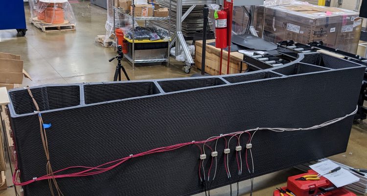
“One of the exciting things that we are doing with the current technology is embedding self-heating nichrome wires inside thermoplastic tools during the extrusion process,” says Ahmed Arabi Hassen, group leader, Composites Innovation Group at Oak Ridge National Laboratory.